-
Keeping Your SUV’s Engine Healthy: Everything You Need to Know About Premium Air Filtration
2026-01-27
Maintaining a modern vehicle often feels like managing a high-tech computer on wheels. Between software updates and battery health, it’s easy to overlook the fundamental components that keep the mechanical heart of your car beating. One of the most common que...rede more -
Is Your Engine Gasping for Breath? Why This Tiny Component Is the Secret to Vehicle Longevit
2026-01-20
When it comes to car maintenance, most drivers immediately think of oil changes, tire rotations, or brake pads. However, there is a "silent hero" tucked away under the hood that determines exactly how well your car performs on a daily basis. Automotive experts...rede more -
Is Your Engine Breathing Properly? The Essential Guide to Premium Air Filtration
2026-01-13
Maintaining a luxury vehicle is about more than just keeping the paint shiny; it is about ensuring the high-performance heart of the machine—the engine—is protected from the elements. For owners of premium German-engineered vehicles, one component often overlo...rede more
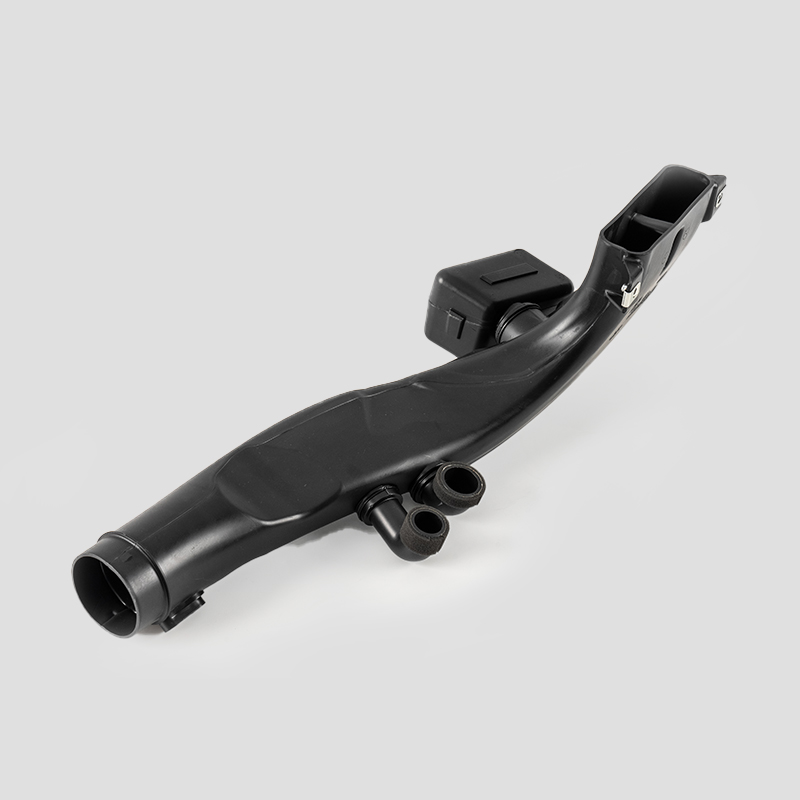
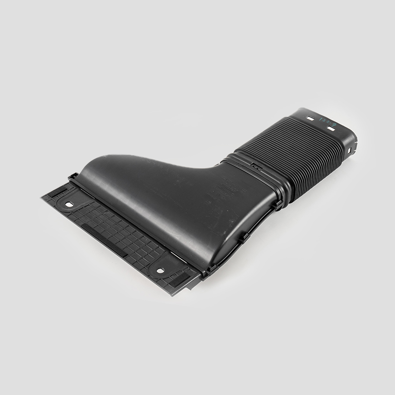
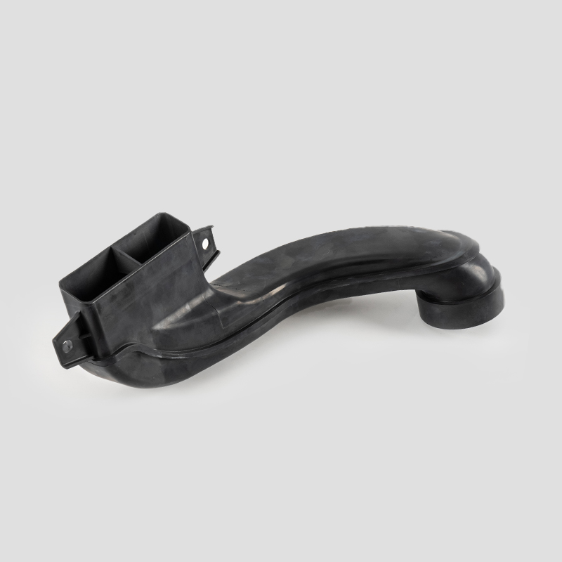
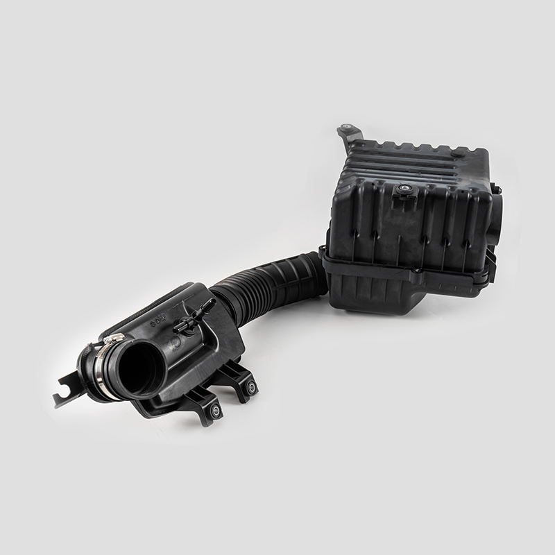
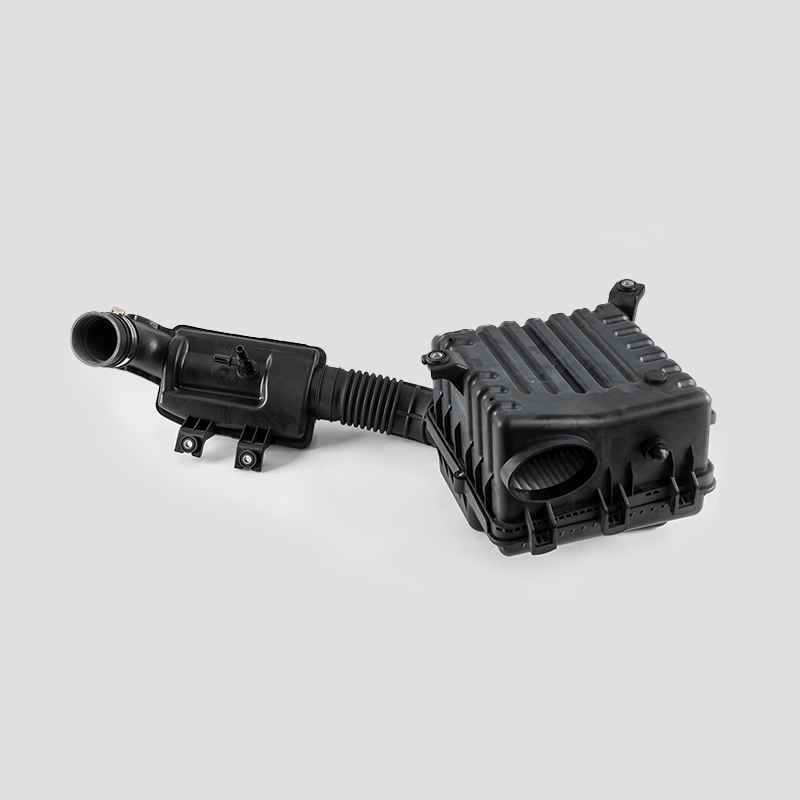
Automotive Engine Air Filtration Intake Tube System Housing Assembly Manufacturer
The automotive engine air filter intake tube system is designed to effectively filter dust and impurities in the air, increase the purity of air entering the combustion chamber, and ensure adequate fuel combustion.
WHO ARE WE?
Ningbo Heyuan Auto Parts Co., Ltd. is an integrated trade and manufacturing enterprise specializing in the production of various filters, including air filters, cabin filters, oil filters, diesel filters, gasoline filters, hydraulic filters, and special filters. NBHY produces over 50 million vehicle filtration systems and various filter elements annually, utilizing advanced plastic blow molding, rubber processing, and welding technologies, making it a diversified large-scale manufacturing base in China.
As a professional OEM Automotive Engine Air Filtration Intake Tube System Housing Assembly Manufacturer and ODM Automotive Engine Air Filtration Intake Tube System Housing Assembly Company, With 30 years of professional design and production experience, NBHY is equipped with modern large-scale production workshops, R&D, business, and office centers, we have strict production, testing equipment and assembly lines. All product development is carried out using computer-aided design, while production strictly adheres to the ISO/TS16949:2009 and ISO9001:2000 quality management systems. Our product quality is highly praised by customers domestically and internationally, with products exported to over a dozen countries and regions, including Europe, the Middle East, and Japan.
Currently, the company mainly provides processing and production services for domestic OEMs and well-known international brands, including over a dozen Fortune 500 companies, and has become an important supplier of filtration systems in China.
-

Industry Experience
0+ -

Modern Intelligent Factory
0+ -

Cooperating Automobile Enterprises
0+ -

Technical Engineers
0+
/ KEEP IN TOUCH
Feel free to ask for any info on NBHY.We are committed to understanding your needs and providing you with the right solution. Our experts will respond to all inquiries within 12 hours.
News
How the design of the Automotive Engine Air Filtration Intake Tube System Housing Assembly considers the integration and use of sensors
1. Sensor interface design
Specialized interface: The Automotive Engine Air Filtration Intake Tube System Housing Assembly usually has a dedicated interface or hole for installing airflow sensors or temperature sensors to ensure that the sensors can be installed securely.
Standardized size: The interface size and location usually follow industry standards to facilitate compatibility with different vehicle models and sensor types.
2. Sensor location optimization
Airflow path: The location design of the sensor takes into account the uniformity of the airflow to ensure that the sensor can work under stable airflow conditions and improve the accuracy of the measurement.
Avoid interference: The location of the sensor should be away from heat and vibration sources to reduce the interference of external factors on the sensor performance.
3. Protection design
Dustproof and waterproof: The design of the Automotive Engine Air Filtration Intake Tube System Housing Assembly takes into account the protection of the sensor, and adopts a sealed design to prevent dust, moisture or oil from entering, ensuring the long-term reliability of the sensor.
Anti-vibration structure: Add anti-vibration and shock absorption functions to the design to protect the sensor from vibration and extend its service life.
4. Electrical Connection and Wiring
Integrated Cable Channels: Design cable channels or guide grooves to facilitate sensor cable connections and ensure safe and neat connections.
Connector Location: Ensure that sensor connectors are easily accessible for maintenance and replacement.
5. Sensor Compatibility
Multi-Sensor Design: The design of the Automotive Engine Air Filtration Intake Tube System Housing Assembly may support multiple types of sensors, such as airflow sensors, temperature sensors, and pressure sensors to meet different engine management needs.
Flexibility and Scalability: The design considers possible future technology upgrades to ensure that it can adapt to the integration of new sensors.
6. Testing and Verification
Functional Testing: After the design is completed, actual installation and functional testing are carried out to ensure the working effect and reliability of the sensor in the intake tube housing.
Data Collection: During the development process, sensors are used for data collection and analysis to optimize the design parameters of the intake tube.


 English
 Español
 عربى
عربى