


 English
 Español
 عربى
عربى
Intercooler Intake and Outlet Pipe Assembly – Blow Molded Components for Turbocharged Engines
Content
- 1 Company Overview: Ningbo Heyuan Auto Parts Co., Ltd.
- 2 How an Intercooler Intake and Outlet Pipe Assembly Works
- 3 Material Selection for Automotive Blow Molding Components
- 4 Temperature Profile Along the Turbo-to-Intercooler Circuit
- 5 Wall Construction Suitability Across Design Priorities
- 6 Platform Coverage for Intercooler Pipe Assemblies
- 7 Practical Guidance for Sourcing Intercooler Pipe Assemblies
- 8 Frequently Asked Questions
An automotive blow molding component used in an intercooler intake pipe assembly or intercooler outlet pipe assembly has to survive a demanding combination of high temperature, pressure pulsation, and constant vibration while keeping the turbocharged air path completely sealed. The intercooler intake pipe assembly is used to deliver the high-temperature air compressed in the turbocharger to the intercooler, and the outlet pipe assembly then carries the cooled, denser air onward to the intake manifold, so any leak or wall failure in either pipe directly reduces boost pressure and engine efficiency. This article explains how these blow-molded pipe assemblies are constructed, what typically happens to air temperature and pressure as it moves through the turbo-to-intercooler circuit, and how platform-specific designs such as the Chery T1J-F26 Jetway off-road vehicle intercooler intake pipe differ from general-purpose pipe assemblies. It is intended for procurement teams, aftermarket buyers, and vehicle engineering staff sourcing intercooler piping components who want technically grounded guidance rather than a generic product listing. Several data visualizations are included to make material selection, thermal behavior, and platform coverage easier to interpret at a glance.
Company Overview: Ningbo Heyuan Auto Parts Co., Ltd.
Ningbo Heyuan Auto Parts Co., Ltd. is a trade and manufacturing enterprise specializing in the production of various filters, with an annual output of over 50 million filtration assemblies and filters. As a professional automobile filter parts manufacturer in China, the company adopts advanced plastic blow molding, rubber processing, and welding technology, supported by a modern production workshop and R&D center. The production process strictly observes the ISO/TS16949:2009 and ISO9001:2000 quality management systems, and the same blow molding and process control capability that supports the company's filtration assemblies also underpins its automotive blow molding component product line, including intercooler intake and outlet pipe assemblies. This shared manufacturing foundation is relevant because both filtration housings and intercooler piping demand similar attention to wall thickness consistency, dimensional accuracy, and joint integrity, even though the two product families serve different functions in the vehicle.
How an Intercooler Intake and Outlet Pipe Assembly Works
The intercooler intake pipe assembly is used to deliver the high-temperature air compressed in the turbocharger to the intercooler, where the air is cooled before it continues into the engine. Air entering a turbocharger is compressed to increase the mass of oxygen delivered to the cylinders, and this compression process raises the air temperature considerably as a byproduct of the compression work performed by the turbine. The intercooler intake pipe carries this hot, pressurized air from the turbocharger outlet to the intercooler core, where heat is removed through the core's finned construction before the air is routed onward. The intercooler outlet pipe assembly then carries the cooled, denser air from the intercooler core to the throttle body or intake manifold, completing the circuit. Because both pipes operate under positive pressure and repeated thermal cycling, an automotive blow molding component used in this application needs to maintain dimensional stability and a reliable seal at every clamped joint along the route.
No product photograph was provided for this article, so the diagram above is a labeled isometric schematic rather than an actual photo of a specific part, and it is intended to show the general air path from the turbocharger through the intake pipe, intercooler core, outlet pipe, and finally the throttle body and intake manifold. This kind of schematic view helps clarify why the intake pipe and outlet pipe are engineered differently from one another, since the intake pipe must tolerate significantly higher air temperature than the outlet pipe, which handles air after it has already been cooled by the intercooler core.
Material Selection for Automotive Blow Molding Components
Blow molding is a common manufacturing process for intercooler intake and outlet pipe assemblies because it can produce complex, curved, hollow geometries in a single piece, which reduces the number of joints along the air path compared with pipes assembled from multiple straight sections. Common materials used for automotive blow molding components in this application include glass-fiber-reinforced polyamide compounds, such as PA6-GF30 and PA66-GF30, as well as multilayer thermoplastic constructions that combine an inner heat-resistant layer with an outer structural layer. Glass-fiber reinforcement generally improves dimensional stability under heat and pressure compared with unreinforced polyamide, which matters most for the intake pipe section closest to the turbocharger outlet where air temperature is highest. Multilayer constructions can allow a design to balance heat resistance, weight, and cost by using a higher-performance compound only where it is functionally needed, rather than throughout the entire pipe length. Selecting the right material combination for a given pipe section is one of the more consequential engineering decisions in the design of a reliable intercooler pipe assembly.
The horizontal bar chart below compares three common blow molding material approaches used for intercooler pipe assemblies, PA6-GF30, PA66-GF30, and multilayer thermoplastic construction, across an illustrative heat resistance rating on a general 0 to 10 scale. This chart is intended to represent commonly discussed relative material characteristics in automotive plastics engineering rather than a certified test result for any specific compound formulation. The horizontal bar format was chosen because it allows a straightforward left-to-right comparison of a single performance dimension across multiple material options. Reading the bars shows that reinforced polyamide compounds generally offer a meaningful heat resistance advantage over less specialized thermoplastic constructions. This comparison is a useful starting point before a detailed material selection discussion with an automotive blow molding component supplier for a specific platform.
The chart shows PA66-GF30 generally rating highest for heat resistance among the three material approaches compared, which is consistent with polyamide 66's higher melting point and better retention of mechanical properties at elevated temperature relative to polyamide 6. PA6-GF30 rates slightly lower but still performs considerably better than a general multilayer thermoplastic construction that does not use a glass-fiber-reinforced polyamide as its primary structural layer. Multilayer thermoplastic constructions rate lowest for pure heat resistance in this illustrative comparison, but they can still be an appropriate choice for the outlet pipe section, where air temperature has already been reduced by the intercooler core and heat resistance is a less dominant design driver than weight or cost efficiency. This pattern generally supports a common design approach in which the intercooler intake pipe assembly, which handles hotter air directly from the turbocharger, is specified in a higher heat resistance material such as PA66-GF30, while the intercooler outlet pipe assembly can sometimes use a more moderate material specification. Glass-fiber reinforcement also generally improves resistance to creep deformation under sustained pressure, which is relevant because the pipe wall is under continuous positive pressure whenever the turbocharger is producing boost. Wall thickness and rib design work alongside material selection to manage pressure retention, so material choice should not be evaluated in isolation from the pipe's structural geometry. For platform-specific designs such as the Chery T1J-F26 Jetway off-road vehicle intercooler intake pipe, off-road use conditions can introduce additional vibration and impact exposure that further reinforce the case for a higher-performance reinforced polyamide compound. Selecting a lower-cost material without adequate heat resistance margin can lead to gradual wall softening or dimensional creep over the pipe's service life, particularly in the intake pipe section nearest the turbocharger outlet. This is why a manufacturer producing automotive blow molding components typically maintains multiple material grade options rather than a single standard compound for all pipe applications. Buyers requesting a new or replacement intercooler pipe assembly should specify the expected boost pressure range and typical operating temperature at the pipe location so the manufacturer can recommend an appropriately matched material grade.
Temperature Profile Along the Turbo-to-Intercooler Circuit
Understanding how air temperature changes along the turbo-to-intercooler circuit helps explain why the intake pipe and outlet pipe assemblies are engineered to different thermal specifications rather than being treated as identical components. Air entering the turbocharger compressor is raised significantly in temperature as a direct result of compression work, and this heated, pressurized air is what flows through the intercooler intake pipe assembly on its way to the intercooler core. Inside the intercooler core, heat is transferred from the compressed air to the surrounding ambient airflow or coolant, depending on the intercooler design, which substantially reduces the air temperature before it exits into the outlet pipe. The outlet pipe assembly then carries this cooler, denser air onward to the throttle body and intake manifold, where the reduced temperature contributes to improved combustion efficiency compared with uncooled compressed air. This general temperature reduction pattern is a well-established principle in turbocharged engine design and is the fundamental reason intercooling exists as a system in the first place.
The area chart below illustrates a generalized, non-brand-specific temperature profile along the turbo-to-intercooler circuit, from the turbocharger outlet through the intake pipe, intercooler core, and outlet pipe, to the throttle body inlet. This is intended as a general conceptual illustration of the well-documented intercooling temperature reduction principle rather than a measured dataset from a specific vehicle or test bench. The area chart format was chosen because it visually emphasizes the magnitude of temperature change across each stage of the circuit in a way that is easy to read even without axis-by-axis analysis. Reading the chart from left to right shows a sharp temperature rise at the turbocharger, a relatively stable high-temperature plateau through the intake pipe, a significant drop through the intercooler core, and a lower, more stable temperature through the outlet pipe. This general shape is useful context for understanding why intake pipe material selection prioritizes heat resistance more heavily than outlet pipe material selection.
The chart shows a steep rise in illustrative air temperature at the turbocharger outlet, consistent with the well-known thermodynamic effect of compressing air, which converts a portion of the compression work into heat. Temperature remains elevated and relatively stable through the intake pipe section, reflecting the pipe's role as a transport path rather than a cooling component, which is why intake pipe material selection prioritizes sustained heat tolerance rather than heat dissipation. The steep downward slope through the intercooler core represents the core's designed function of removing heat from the compressed air before it continues toward the engine, and this stage is where the majority of the temperature reduction in the entire circuit takes place. Temperature stabilizes at a lower level through the outlet pipe, which is consistent with the earlier material comparison showing that outlet pipe applications can often tolerate a somewhat less heat-resistant material specification than the intake pipe. The temperature profile remains relatively flat approaching the intake manifold, reflecting minimal additional heat gain over the short remaining distance in a well-designed piping layout. This general pattern is widely referenced in turbocharged engine and intercooling system literature, since the core purpose of an intercooler is precisely this compression-then-cooling temperature curve. Understanding this profile also explains why clamp and joint integrity at the intake pipe connections deserves particular attention, since repeated thermal expansion and contraction at the hottest section of the circuit can gradually loosen a poorly designed joint over time. For platform-specific applications such as the Chery T1J-F26 Jetway off-road vehicle intercooler intake pipe, additional vibration from off-road operating conditions compounds this thermal cycling stress, reinforcing the case for robust joint design at the turbocharger connection point. Buyers specifying a replacement or custom intercooler pipe assembly can use this general temperature profile concept to communicate more precisely which pipe section requires the highest heat resistance material grade. This kind of shared conceptual understanding between buyer and manufacturer generally leads to a more accurately specified automotive blow molding component on the first design iteration.
Wall Construction Suitability Across Design Priorities
Beyond base material selection, intercooler pipe assemblies can be constructed as a single-layer wall or as a multilayer wall combining different material properties at different depths through the pipe wall. Choosing between these construction approaches involves weighing several design priorities at once, including heat resistance, pressure retention, weight, and cost efficiency, and no single construction type is optimal across every priority simultaneously. A single-layer glass-fiber-reinforced polyamide wall generally offers strong heat resistance and pressure retention in a straightforward manufacturing process, while a multilayer wall can be engineered to place a heat-resistant compound only at the inner surface, potentially reducing overall material cost and weight. Corrosion resistance is less of a concern for these polymer-based pipe assemblies than it would be for a metal pipe, but resistance to fuel vapor and oil mist exposure in the engine bay is still a relevant consideration for material selection. Comparing these construction approaches across multiple design priorities at once is where a matrix-style visualization becomes particularly useful.
The heatmap below compares single-layer reinforced polyamide construction against multilayer thermoplastic construction across four illustrative design priorities: heat resistance, pressure retention, weight efficiency, and cost efficiency, using a general qualitative suitability scale. This is intended as a conceptual illustration of common trade-off patterns discussed in automotive plastics engineering rather than a certified performance comparison for any specific product line. The heatmap format was chosen because it allows two construction types to be compared across four dimensions simultaneously in a single compact grid, which is more efficient to read than four separate bar charts. Darker shading in the grid represents a stronger general suitability rating for that combination of construction type and design priority. This comparison is intended to support a more informed conversation between a buyer and an automotive blow molding component manufacturer about which construction approach best matches a specific platform's priorities.
The heatmap shows single-layer reinforced polyamide construction generally rating strongest for heat resistance and pressure retention, which is consistent with the earlier material comparison chart and reflects the benefit of a uniformly reinforced wall under sustained thermal and pressure load. Multilayer thermoplastic construction generally rates stronger for weight efficiency and cost efficiency, since it can concentrate higher-cost, heavier reinforced material only where functionally necessary rather than throughout the full pipe wall. This trade-off pattern illustrates why the choice between single-layer and multilayer construction is rarely a matter of one approach being universally better, and instead depends on which design priorities matter most for a specific platform and pipe location. For the intake pipe section closest to the turbocharger, where heat resistance and pressure retention are the dominant concerns based on the temperature profile discussed earlier, single-layer reinforced polyamide construction is often the more straightforward choice. For the outlet pipe section, where temperature has already been reduced by the intercooler core, multilayer construction can be a reasonable way to manage weight and cost without a significant compromise in performance for that location. Off-road platform applications, such as the Chery T1J-F26 Jetway off-road vehicle intercooler intake pipe, generally favor the stronger pressure retention and heat resistance profile of single-layer construction given the additional vibration and thermal cycling stress associated with off-road use. Passenger vehicle applications with more moderate duty cycles may have more flexibility to consider multilayer construction where weight reduction is a meaningful design goal. This kind of construction-versus-priority framework is a useful starting point for a technical discussion with a manufacturer, but final selection should always be confirmed against the specific platform's boost pressure, operating temperature range, and duty cycle. Weight efficiency has become an increasingly relevant priority across the automotive industry generally, since reducing component weight contributes to overall vehicle efficiency goals, which is one reason multilayer construction has gained broader adoption in less thermally demanding pipe sections. Ultimately, the construction choice should be made in consultation with an automotive blow molding component manufacturer that can validate the selected approach against the specific pressure and temperature requirements of the platform in question.
Platform Coverage for Intercooler Pipe Assemblies
Intercooler intake pipe assemblies and intercooler outlet pipe assemblies are generally engineered as platform-specific parts, since each vehicle's engine bay layout, turbocharger position, and intercooler mounting location require a distinct pipe routing and connection geometry. A dedicated design such as the Chery T1J-F26 Jetway off-road vehicle intercooler intake pipe reflects this platform-specific engineering approach, where the pipe route and mounting points are matched to that particular vehicle's chassis and engine bay layout. General Chery intercooler intake pipe assembly and intercooler outlet pipe assembly designs cover related models sharing similar platform architecture, while broader general-purpose intercooler intake pipe assembly and intercooler outlet pipe assembly designs support a wider range of passenger and light commercial vehicle applications. Table 1 below summarizes these platform categories to help buyers quickly identify the correct pipe assembly category for their sourcing needs.
| Platform Category | Typical Assembly | Duty Consideration |
|---|---|---|
| Chery T1J-F26 Jetway | Chery T1J-F26 Jetway Off-Road Vehicle Intercooler Intake Pipe | Off-road, higher vibration exposure |
| Chery (general) | Chery Intercooler Intake Pipe Assembly | On-road passenger duty |
| General passenger platform | Intercooler Intake Pipe Assembly | Standard on-road duty |
| General passenger platform | Intercooler Outlet Pipe Assembly | Standard on-road duty |
This platform categorization reflects a general engineering pattern common across the automotive blow molding component industry, where off-road and higher-duty-cycle applications typically warrant more conservative material and construction choices than standard on-road passenger applications. Matching the pipe assembly category to the actual duty conditions of the platform is one of the more reliable ways to avoid premature pipe wall fatigue or joint failure. Buyers sourcing a Chery T1J-F26 Jetway off-road vehicle intercooler intake pipe or a general Chery intercooler intake pipe assembly should confirm which duty category applies to their specific application before finalizing a design, since the difference in expected vibration and thermal cycling can meaningfully affect the appropriate material and wall construction recommendation discussed in the previous two sections.
Practical Guidance for Sourcing Intercooler Pipe Assemblies
Sourcing an accurate intercooler intake pipe assembly or intercooler outlet pipe assembly starts with gathering the platform, routing, and operating condition details a manufacturer needs to confirm or develop a matching design. The checklist below summarizes the information most commonly requested when working with an automotive blow molding component manufacturer on a new or replacement intercooler pipe assembly.
- Exact vehicle platform, model year range, and turbocharger or engine variant
- Existing pipe assembly part number or physical sample dimensions, if available
- Approximate boost pressure range and expected air temperature at the intake pipe location
- Routing path and mounting or clamp points within the engine bay
- Duty classification, such as standard on-road or off-road with higher vibration exposure
- Expected order volume and whether new mold tooling development is required
Providing this information at the outset generally shortens the design confirmation or tooling development timeline, since it reduces the number of clarifying rounds needed before a manufacturer can propose a matched material and construction specification. This is particularly relevant for platform-specific designs such as the Chery T1J-F26 Jetway off-road vehicle intercooler intake pipe, where routing geometry and duty conditions differ meaningfully from a general passenger platform intercooler intake pipe assembly.
Frequently Asked Questions
Q1: What is the difference between an intercooler intake pipe assembly and an outlet pipe assembly?
The intake pipe assembly delivers hot, compressed air from the turbocharger to the intercooler, while the outlet pipe assembly carries the cooled air from the intercooler onward to the throttle body or intake manifold. The intake pipe generally requires higher heat resistance due to its exposure to hotter air.
Q2: What is an automotive blow molding component in this context?
It generally refers to a hollow plastic part, such as an intercooler intake or outlet pipe, produced through the blow molding process to form a complex curved shape in a single piece with minimal joints along the air path.
Q3: Why does the Chery T1J-F26 Jetway off-road intercooler intake pipe need a different specification than a general design?
Off-road use generally introduces higher vibration and more variable thermal cycling than standard on-road duty, which typically favors a single-layer, heat-resistant reinforced polyamide construction with stronger pressure retention characteristics.
Q4: Can a multilayer construction be used for the intake pipe as well as the outlet pipe?
It is possible, but the intake pipe's higher temperature exposure generally favors single-layer reinforced polyamide construction for stronger heat resistance and pressure retention, while multilayer construction is more commonly considered for the cooler outlet pipe section.
Q5: Can Ningbo Heyuan Auto Parts develop a new intercooler pipe design for a platform not listed in this article?
Yes, new mold tooling and pipe assembly designs are generally developed on an ongoing basis to support additional platforms, based on accurate routing, boost pressure, and duty condition information supplied by the buyer.
Related Products
-
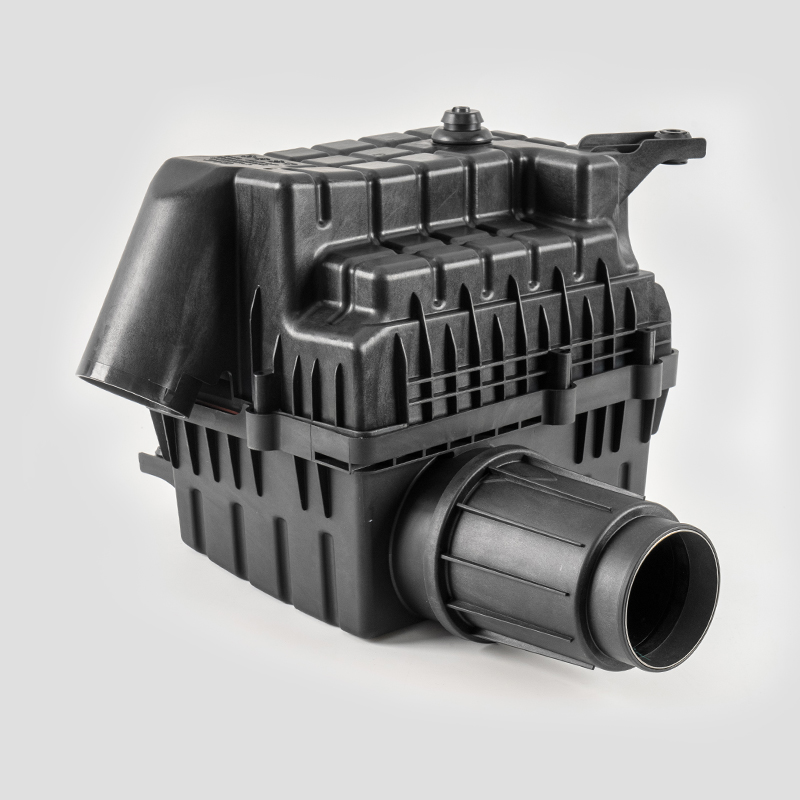
GAC A57 Automotive Engine Air Filtration System Housing Assembly
-
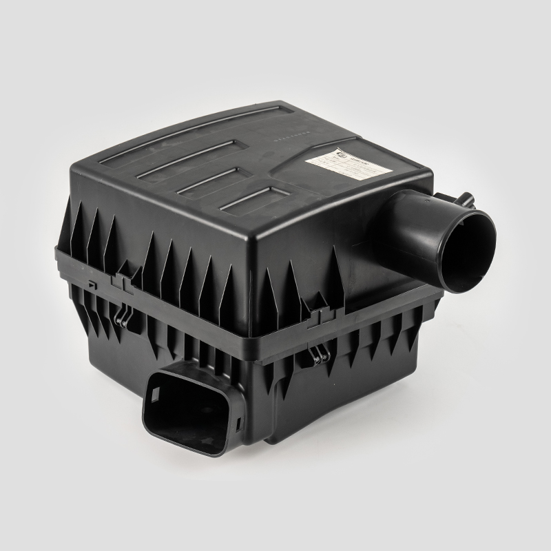
Great Wall A30 Automotive Engine Air Filtration System Housing Assembly
-
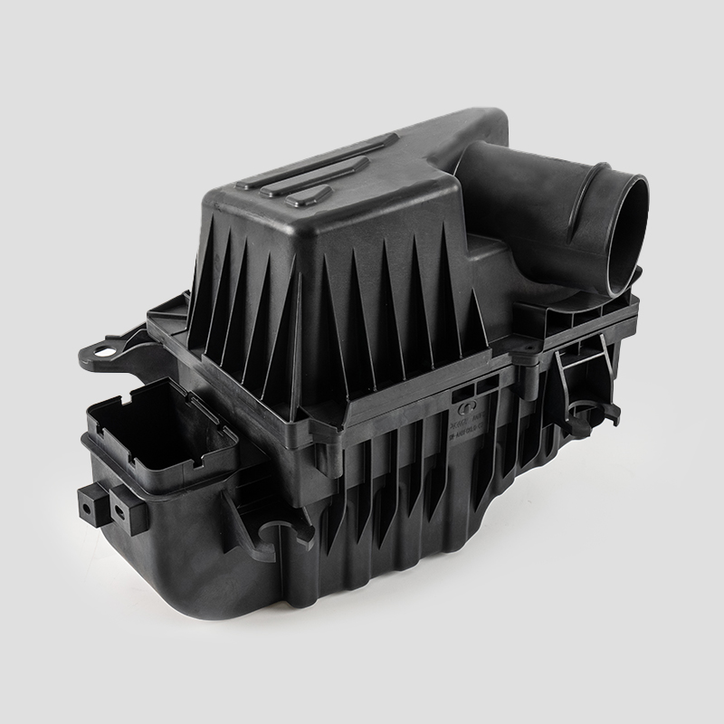
Great Wall B30 Automotive Engine Air Filtration System Housing Assembly
-
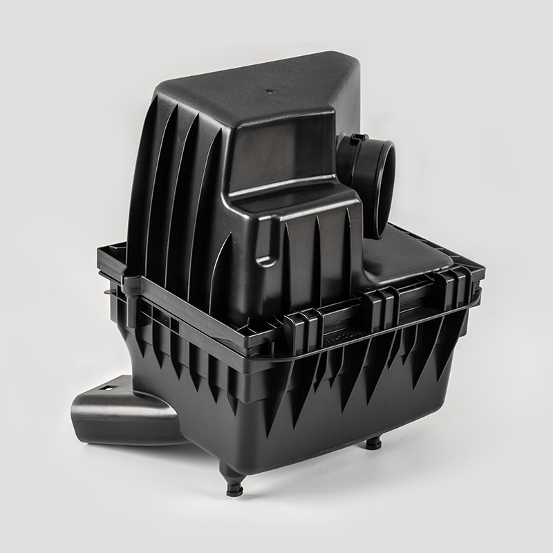
Great Wall Automotive Engine Air Filtration System Housing Assembly
-
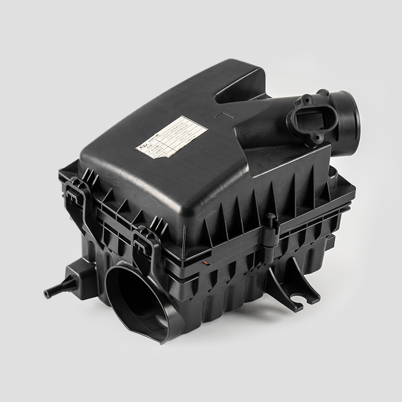
BAIC Automotive Engine Air Filtration System Housing Assembly
-
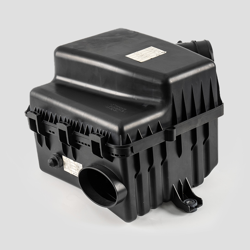
BAIC SUV Automotive Engine Air Filtration System Housing Assembly



Copyright © Ningbo Heyuan Auto Parts Co., Ltd. Rights Reserved. Custom Automobile Filter Parts Company OEM/ODM Automobile Filter Parts Manufacturer
